Hello everyone,
today I was playing with my new Raspberry Pi 2 running Windows 10 IoT Core and I am pretty excited about the way it works and how awesome it is to build apps for it.
I am going to use it to build a maze solving robot for ITU Robot Competition which takes place in Istanbul, Turkey every year.
What will we need?
- Raspberry Pi 2
- HC-SR04 Ultrasonic Sensor
- Breadboard
- Female-to-Female Jumper Wires
- Resistor 1kΩ
- Resistor 2kΩ
What is a Raspberry Pi?
The Raspberry Pi is a computer that is very cheap and quite small. It has hardware pins called GPIO pins that allow you to connect all manor of sensors, control boards, and other things. The GPIO pins can then be accessed directly by your code.

What is an HC-SR04 Ultrasonic Sensor?
It’s a cheap sensor that can be used to measure the distance between itself and an object in front of it by sending an ultrasonic pulse and listening for its echo. The HC-SR04 can be connected to many things including the Raspberry Pi.

Why do I need the resistors?
The sensor’s output signal (ECHO) is rated at 5V. However, the input pins on the Raspberry Pi GPIO are rated at 3.3V.
Sending a 5V signal into that unprotected 3.3V input pin could damage the GPIO pin of the Raspberry Pi 2, which is something we want to avoid! We’ll need to use a small voltage divider circuit, consisting of two resistors, to lower the sensor output voltage to something our Raspberry Pi can handle.
A voltage divider consists of two resistors (R1 and R2)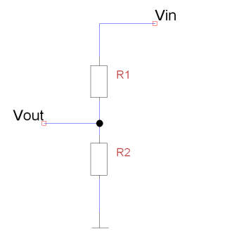 in series connected to an input voltage (Vin), which needs to be reduced to our output voltage (Vout). In our circuit, Vin will be ECHO, which needs to be decreased from 5V to our Vout of 3.3V.
-
Hardware part
There are four pins on the HC-SR04 sensor. The pin labelled VCC requires connecting to a 5V pin, the pin labelled “Gnd” requires connecting to a ground pin, and the pins “Trig” and “Echo” need to be each wired to a unique GPIO pin on the Raspberry Pi.
I am going to use the following pins:
VCC -> 2nd pin
TRIG-> 12th pin
ECHO-> 16th pin
GND -> 6th pin

I think it is pretty straight-forward (and I am not a hardware guy 🙂 ) so I am gonna leave it as it is, hope you don’t mind.
-
Software part
Here is the easy, yet cool part. Note that, you can use the exactly same code for every board running Windows 10. ( Raspberry Pi 2, MinnowBoard Max, DragonBoard410c)
Developing for Windows 10 on these boards gives us a bunch of options. From UWP App (which I am going to build today) to Express Node.js Web App.
The first thing you have to do is to setup your environment. I am not going to dive into this as there is a detailed tutorial on Microsoft IoT GitHub page, HERE.
Assuming that you have already set up your environment, it’s time to start coding!
First, let’s create a new Blank Universal Windows App by going to
File -> New -> Project -> Installed -> Visual C# -> Windows -> Universal -> Blank App (Universal Windows)
You can name it as you like, I named it IoTUltrasonicApp.
Now you have to add a reference to Windows IoT Extensions for the UWP in your newly created project. Right click on the References section and click Add Reference… Then you will find it under
Universal Windows -> Extensions
Click on Windows IoT Extensions for the UWP tick it and press OK.

Time to add two TextBlocks to our MainPage.xaml file. The one of them will be used to present the calculated distance and the other to present the status of the our GPIO Controller / Pins. I just drag ‘n’ drop them somewhere on my page.

Here is the code of my Grid for a quick copy / paste.
<Grid Background="{ThemeResource ApplicationPageBackgroundThemeBrush}">
<TextBlock x:Name="gpioStatus" FontSize="20" HorizontalAlignment="Left" Margin="10,531,0,0" TextWrapping="Wrap" Text="Status" VerticalAlignment="Top"/>
<TextBlock x:Name="distancetb" FontSize="20" HorizontalAlignment="Left" Margin="453,299,0,0" TextWrapping="Wrap" Text="0" VerticalAlignment="Top"/>
</Grid>
Now, let’s open MainPage.xaml.cs.
Use the following namespaces
using Windows.Devices.Gpio;
using System.Threading.Tasks;
using System.Diagnostics;
Let’s declare our variables and constraints. I am gonna explain them all soon.
private const int ECHO_PIN = 23;
private const int TRIGGER_PIN = 18;
private GpioPin pinEcho;
private GpioPin pinTrigger;
private DispatcherTimer timer;
private Stopwatch sw;
The 2 int constraints are the number of the pins (something like ID) I use for the echo and the trigger I/O of my ultrasonic sensor. You can find them in the raspberry image above. (GPIO X, the X is the number we need.)
The GpioPin objects represents the pins we will use to write to and read from the sensors.
Also, we are going to compute the distance frequently so we need a timer. For that purpose I am gonna use a DispatherTimer.
The Stopwatch is going to be used to calculate the distance.
public MainPage()
{
this.InitializeComponent();

InitGPIO();

timer = new DispatcherTimer();
timer.Interval = TimeSpan.FromMilliseconds(400);
timer.Tick += Timer_Tick;
if (pinEcho != null && pinTrigger != null)
{
timer.Start();
}

}
We first initialize our GPIO, and if the initialization is successful, we start our timer at 400ms interval.
private async void InitGPIO()
{
var gpio = GpioController.GetDefault();
if (gpio == null)
{
pinEcho = null;
pinTrigger = null;
gpioStatus.Text = "There is no GPIO controller on this device.";
return;
}

pinEcho = gpio.OpenPin(ECHO_PIN);
pinTrigger = gpio.OpenPin(TRIGGER_PIN);

pinTrigger.SetDriveMode(GpioPinDriveMode.Output);
pinEcho.SetDriveMode(GpioPinDriveMode.Input);
gpioStatus.Text = "GPIO controller and pins initialized successfully.";

pinTrigger.Write(GpioPinValue.Low);

await Task.Delay(100);
}
Here, we get the default GpioController and check if it null. If it is, something is wrong with our board and we can’t communicate with it’s GpioController. If it isn’t, we open the echo and the trigger GPIO in order to use them. We set the DriveMode of the Trigger and Echo pins to Output and Input respectively. That means that we are going to write to the Trigger pin and read from the Echo one. Then, we just turn Trigger off by writing GpioPinValue.Low to it and we wait for 100ms.
And now the tricky part.
private async void Timer_Tick(object sender, object e)
{
pinTrigger.Write(GpioPinValue.High);
await Task.Delay(10);
pinTrigger.Write(GpioPinValue.Low);
sw.Start();
while (pinEcho.Read() == GpioPinValue.Low)
{

}

while (pinEcho.Read() == GpioPinValue.High)
{
}
sw.Stop();

var elapsed = sw.Elapsed.TotalSeconds;
var distance = elapsed * 34000;

distance /= 2;
distancetb.Text = "Distance: " + distance + " cm";
}
To calculate the distance, some things need to be done in the following order.
- Turn the Trigger on to send an ultrasonic wave, wait a bit and turn it off. The ultrasonic wave should hit an object and come back to the sensor.
- Start the timer and wait for the ultrasonic wave to come back to the sensor.
- Stop the timer when Echo doesn’t have anything more to read.
- Multiply the elapsed time with the speed of sound (in cm/s) at sea level.
- Divide by 2 because the ultrasonic wave traveled the current distance twice.
- Voila, we set the text of our TextBlock to the text we need.

That’s it!
Now, you can start playing with your board and create amazing IoT and Robotics things.
Don’t forget to comment below.
Here is my project hosted on GitHub.
I will probably write more IoT and Robotics tutorials like this one in my spare time on my blog or on StudentGuru Tutorials.
Till then, happy coding!
PS. Sorry for bad code formatting, it’s WordPress not me!
Thanks for reading!
George
Oh. Thnx much for your experiences with UWP. I was looking for exactly something like this. I am really interested in developing for W10. Have you got some application in Windows Store?
LikeLiked by 1 person
Hello Kverten!
I am glad that you found it useful! Yeah I have some. 🙂
I mostly develop applications for others nowadays so there isn’t any new one developed by me under my name. Have fun developing for W10!
LikeLike
Hi! I have 8 of these sensors. Will raspberry pi handle all of those? I mean making 8 dispatcher timers in it be okay? 😀
LikeLike
Woah, 8 ultrasonic sensors!? What are you going to make with them?
Yeah, it would be fine. Just don’t forget to use different threads for every one of them. 🙂
Thanks for your comment!
LikeLike
Im having trouble doing this project. I am encountering an error. The error is System.NullReference. Here is my code
using System;
using System.Collections.Generic;
using System.IO;
using System.Linq;
using System.Runtime.InteropServices.WindowsRuntime;
using Windows.Foundation;
using Windows.Foundation.Collections;
using Windows.UI.Xaml;
using Windows.UI.Xaml.Controls;
using Windows.UI.Xaml.Controls.Primitives;
using Windows.UI.Xaml.Data;
using Windows.UI.Xaml.Input;
using Windows.UI.Xaml.Media;
using Windows.UI.Xaml.Navigation;
using Windows.Devices.Gpio;
using System.Threading.Tasks;
using System.Diagnostics;
// The Blank Page item template is documented at http://go.microsoft.com/fwlink/?LinkId=402352&clcid=0x409
namespace Ultrasonic
{
///
/// An empty page that can be used on its own or navigated to within a Frame.
///
public sealed partial class MainPage : Page
{
private const int ECHO_PIN = 23;
private const int TRIGGER_PIN = 18;
private GpioPin pinEcho;
private GpioPin pinTrigger;
private DispatcherTimer timer;
private Stopwatch sw;
public MainPage()
{
this.InitializeComponent();
InitGPIO();
timer = new DispatcherTimer();
timer.Interval = TimeSpan.FromMilliseconds(400);
timer.Tick += Timer_Tick;
if (pinEcho != null & pinTrigger != null)
{
timer.Start();
}
}
private async void Timer_Tick(object sender, object e)
{
pinTrigger.Write(GpioPinValue.High);
await Task.Delay(10);
pinTrigger.Write(GpioPinValue.Low);
sw.Start();
while (pinEcho.Read() == GpioPinValue.Low)
{
}
while (pinEcho.Read() == GpioPinValue.High)
{
}
sw.Stop();
var elapsed = sw.Elapsed.TotalSeconds;
var distance = elapsed * 34000;
distance /= 2;
DistanceTextBlock.Text = “Distance: ” + distance + “cm”;
}
private async void InitGPIO()
{
var gpio = GpioController.GetDefault();
if (gpio == null)
{
pinEcho = null;
pinTrigger = null;
GPIOStatus.Text = “There is no GPIO Controller you motherfucker”;
return;
}
pinEcho = gpio.OpenPin(ECHO_PIN);
pinTrigger = gpio.OpenPin(TRIGGER_PIN);
pinTrigger.SetDriveMode(GpioPinDriveMode.Output);
pinEcho.SetDriveMode(GpioPinDriveMode.Input);
GPIOStatus.Text = “GPIO CONTROLLER AND PINS INITIALIZED CORRECTLY”;
pinTrigger.Write(GpioPinValue.Low);
await Task.Delay(100);
}
}
}
LikeLike
@Reynard Natividad Hello, are your pins set up and initialized correctly?
LikeLike
0 Pingbacks